Program Settings
Program settings affect how ProfiCAD behaves across all documents. Open them via File - Options or press F12. The dialog holds both the program settings and the settings of the current document.
The System group contains these tabs:
Settings that belong to one particular drawing live in the same dialog under the Document group — see Document settings.
System - Paths
Symbol library
Set the root directory where all your symbols are stored (PPD and PICD files).
Documents
The folder with your drawings. The Documents panel lists the drawings stored in this location.
Both paths have a Change... button and an Open in Explorer button, which opens the folder straight in Windows Explorer — handy when you need to rename, move or delete files.
How to Share a Symbol Library Within Your Organization
- Store the symbol library in a shared directory on your network server.
- On each computer, map that network directory as a drive letter.
- In ProfiCAD, set the symbol library path to the mapped drive letter on the "Paths" tab in program settings.
System - Control
Enable undo/redo
Undo/Redo lets you reverse your last action. You can disable this feature here if needed.
Number of steps on zoom change
Zoom transitions are animated to reduce eye strain. A higher value gives smoother animation; a lower value is faster.
Enable auto scrolling
When you move the mouse pointer to the edge of the working area, the drawing automatically scrolls in that direction. You can also toggle scrolling any time with Ctrl+K.
Confirmation when deleting in the drawing
Controls whether a "Delete selected objects?" confirmation dialog appears when you delete objects.
Confirm deletion in symbols panel
The same confirmation for the symbols panel. Here you are deleting files on disk rather than objects in a drawing, so we recommend leaving it on.
Enable ruler
Shows rulers along the top and left edge of the working area. Takes effect after the program restarts.
Esc = deselect all
Press Esc to deselect all selected objects.
Enter text before it is inserted into the drawing
When enabled, the program asks for the text first and inserts it afterwards.
When disabled, the word "Text" is inserted straight away and you edit it later.
Drawing border margin
Sets the distance between the edge of the drawing and the edge of the program window.
System - Symbols
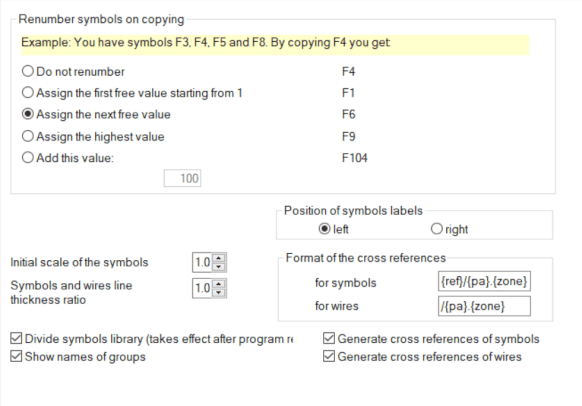
Renumber symbols on copying
How should a copied symbol be renumbered? An example: your drawing contains F3, F4, F5 and F8, and you copy F4. The result depends on the selected mode:
| Do not renumber | F4 |
| Assign the first free value starting from 1 | F1 |
| Assign the next free value | F6 |
| Assign the highest value | F9 |
| Add this value | adds the number you enter |
Position of symbols labels
Determines whether labels (reference, type, value) are drawn to the left or to the right of the symbol. The setting applies to newly inserted symbols.
Initial scale of the symbols
Sets the default size of symbols newly inserted into a drawing.
Symbols and wires line thickness ratio
All line and wire thicknesses are multiplied by this ratio. For example, a ratio of 1.5 turns a 0.2 mm line into a 0.3 mm one.
Divide the symbols library
When enabled, the graphical symbols panel shows a list of main groups, which makes a large library easier to navigate. Takes effect after the program restarts.
Show names of groups
Adds group names to the symbols panel. Without them the panel fits more symbols; with them it is easier to find your way around.
Show "Search Symbols" button
You can also search for symbols with the space bar. If you use that, turn the button off and gain a little more room in the symbols panel.
System - Cross References
Cross-references link places in a drawing that belong together but sit far apart — typically a relay coil and its contacts, or a wire continuing on another page. This tab switches the generation on separately for symbols and for wires, and sets the format the references are written in. The individual options and the format placeholders are described in Cross-reference settings.
System - Others
Units
Choose the units used for object dimensions in the Properties panel: Metric, Imperial (decimal) or Imperial (fractions). The setting also drives the size of the main grid (1 cm or 1").
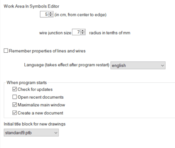
Wire junction size
Sets the size of the dot marking a conductive junction of wires. The value is a radius in tenths of a millimetre.
Initial title block for new drawings
Choose the title block the program inserts automatically into every new drawing. You can change it per drawing later in the document settings.
When program starts
Two independent options decide what happens right after startup:
- Open recent documents — restores the drawings you had open when you last quit,
- Create a new document — opens an empty drawing so you can start straight away.
Language
Changes the program's interface language. Takes effect after the program restarts.
This does not affect the symbol library language. If you accidentally installed the program in the wrong language, uninstall it and reinstall with the correct language.
If you need drawings in multiple languages, install the program separately for each language. Your symbol library will then contain symbols in all languages.
Check for updates
ProfiCAD checks for a newer version each time it starts. If an update is available, it downloads and installs automatically. You'll be prompted to save your work before the program restarts.
Automatic updating works within a major version only — for example from 14.1 to 14.2, never from 14 to 15. An upgrade to a new major version is always a manual step, so nothing you did not ask for gets installed.
System - Wires
Auto-connect symbol over wire
When you place a symbol on top of an existing wire, it automatically connects into that wire. Delete the symbol later, and the original wire is restored.
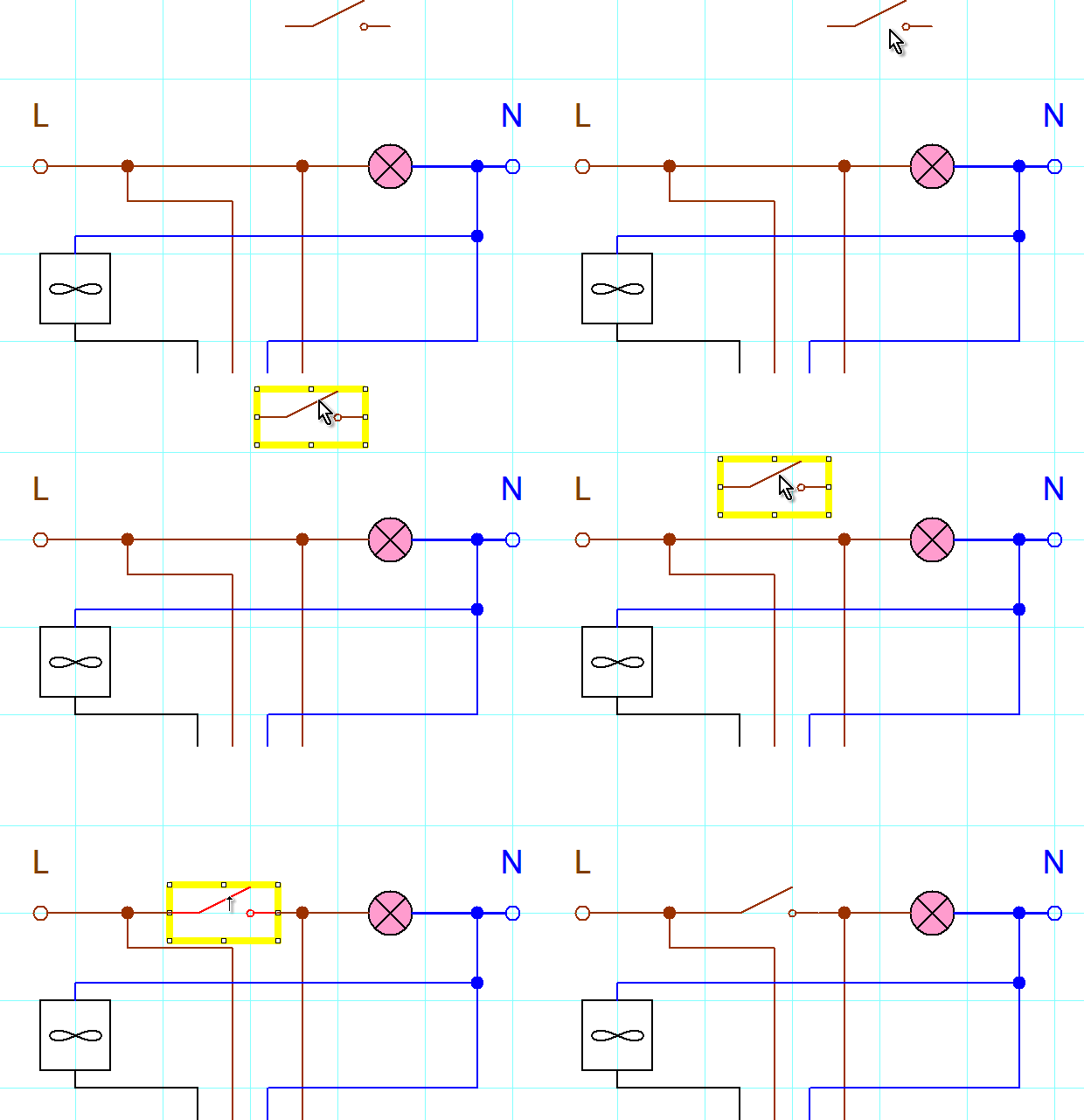
If a symbol doesn't auto-connect, snap might be interfering. Try zooming in and moving the symbol while holding the Shift key to temporarily disable snap.
The companion option and highlight the wire being connected decides whether the wire lights up while you drag a symbol over it. Turn it off and symbols still connect, just without the visual cue.
Wire connection sensitivity
The distance at which a wire end snaps to a connection point of a symbol. A higher value helps in dense diagrams; too high a value may snap the wire to a neighbouring point.
Remember properties of lines and wires
When enabled, any color or thickness changes you make to a line or wire will carry over to the next line or wire you draw.
The new connection adopts the name of the existing connection
A wire drawn onto an already named wire takes over its name. That saves work when numbering wires, because the whole node keeps a single name.
Allow 45° wire segments
Besides horizontal and vertical wires, allows sloping segments at 45°.
Color of cable symbols
The color used for cable symbols. A distinct color makes cables easy to tell apart from ordinary wires.
System - Logging
The program records and sends technical error data to the developers. This information is strictly limited to source code issues -- it never includes personal information or any documents you create.
Logging level
Sets how much detail is recorded, from the most verbose to none:
- Info — records ordinary events too; useful while we are investigating a specific problem with you,
- Warnings — records warnings and errors,
- Errors — records errors only,
- Off — disables logging completely.
Working with the log file
The Log Size field shows how much space the log takes. The buttons below manage it:
Show Log— opens the log file,Delete Log...— clears the recorded data,Test Log— writes a test entry so you can verify that logging works.
System - Backup
Automatically save every ...
A power cut or a system crash can happen any time. Auto-save stores your work at a set interval so you do not lose it. It only works on documents that have been manually saved at least once. The interval is in minutes; 0 turns the feature off.
The "create backup copy with the bak extension" option saves a backup every time the document is saved. Each backup replaces the previous one. Backup files have the .BAK extension and are stored in the same folder as the original.
⚠️ This option does not replace a proper backup !!!
How to Restore a Drawing from a BAK Backup
Say you have a file named "test.sxe" that won't open because it was corrupted:
- Rename "test.sxe" to something else, e.g. "test2.sxe".
- Rename "test.sxe.bak" to "test.sxe".
- You can now open and use "test.sxe".
Archiving
Archiving is stronger protection still. Every time you save a drawing, the program stores a timestamped copy in a special directory. This means you can go back to any previous version of your drawing whenever you need to.
How to set up archiving
Everything you need is on the same Backup tab:
Use the Archive checkbox to enable or disable archiving.
Use the Change... button next to Directory for archiving to choose where archived copies should be stored.
Pick a directory synced via Dropbox, OneDrive, Google Drive, or a similar service. That way your archives are protected even if your disk fails.
How to restore a drawing from an archive
Go to File - Restore from archive. A dialog lists all archived versions -- select the one you want and press OK.
If no archive exists for the current drawing, you'll see the message "No archive is available for this document."
How to delete unnecessary archive copies
On the Backup tab press Open in Explorer. Select the backups you no longer need and press del.
💡 Pro tip: Set archiving up right after you install the program and point it at a cloud-synced folder. That gives you triple protection — auto-save, BAK files and an archive in the cloud.
