Document Settings
Every drawing may have different needs — different fonts, a different title block, differently formatted reports. That is why ProfiCAD keeps a set of settings bound to the current document. Open them via File - Options or press F12.
The Document group only appears in the dialog when a drawing is open. Settings that apply to the whole program regardless of the drawing are described in Program settings.
Here is an overview of the tabs:
Document - Reports
When you print a bill of materials, a netlist or any other output, its appearance matters. This tab sets the look and formatting of all print reports for the current drawing.
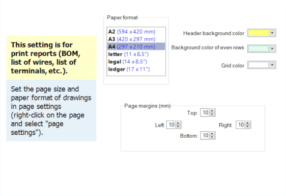
Paper format
Reports are printed independently of the drawing, so they can use a different paper format than the diagram itself — a bill of materials often suits A4 portrait even when the drawing is A3.
Page margins
Report margins in millimetres, separately for left, top, right and bottom.
Colors
Three buttons drive the look of the table:
- Header background — the color of the first row with column names,
- Even rows background — the color of every other row; alternating shades make wide tables easier to read,
- Grid color — the color of the lines between cells.
💡 Pro tip: If you print reports on a monochrome printer, pick very light shades for the backgrounds. A saturated color comes out of a laser printer as dark grey and makes the text above it harder to read.
Document - Fonts
A badly chosen typeface can spoil even a carefully drawn diagram. Here you set the typeface and size for each kind of text so the drawing stays legible.
The "Letterings" and "Texts" settings here are just defaults -- you can override them individually for each text later.
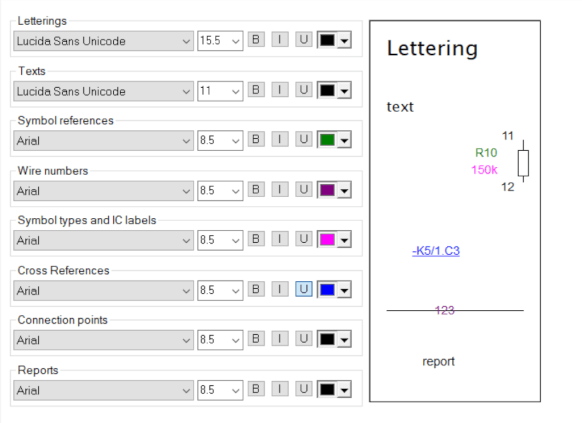
Fonts are set separately for eight kinds of text:
| Group | What it covers |
|---|---|
| Letterings | standalone letterings inserted via Insert - Lettering |
| Texts | multi-line texts in the drawing |
| Symbol types and IC pin labels | the type of a symbol and the pin labels of integrated circuits |
| Symbol references | symbol designations such as -K1 |
| Cross references | the references described under Cross References |
| Connection points | connection point numbers |
| Reports | text in the bill of materials and other reports |
| Wire numbers | labels carrying wire numbers |
Document - Variables
Variables are text values filled automatically into the title block of a drawing. Enter the project name, the customer or the order number here, and the values appear everywhere the title block refers to them.
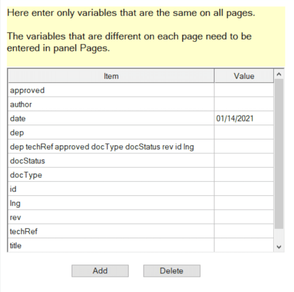
Use Add to create a variable and Delete to remove the selected one. The program offers the variables matching the fields of the chosen title block, so usually you only fill in the values.
Document - Description
Sometimes you need to note things that do not belong in the diagram itself — remarks about the design, unfinished ideas or instructions for a colleague. This tab is a notepad inside the document.
Document - Title block
This tab switches the title block on, selects its file, sets its position on the page (bottom, left or right) and the distance from the edges. What the individual buttons do is described in Title Block for Technical Drawings.
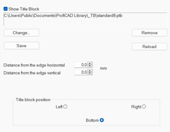
Document - Reference grid
This tab decides which edges the grid is drawn along, how large the individual fields are and how zones are labelled. It is all described in Reference Grid.
Document - Wire numbering
This tab switches automatic numbering on and sets where and how the numbers appear in the drawing. It is all described in Wire numbering.
