Reference Grid
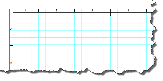
On large drawings it is easy to get lost — that is what the reference grid is for. It is shown along the edges of the drawing and lets you describe the position of any component precisely. Turn it on in the settings: F12 - Document - Reference Grid. You can choose which edges the grid is shown along and optionally turn on centering marks.
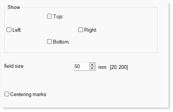
The individual options
Show
Four independent checkboxes decide which edges of the page the grid is drawn along — top, left, right and bottom. All four are the usual choice; on narrow drawings two are enough.
Field size
The width of a single grid field in millimetres, between 20 and 200 mm. Smaller fields give a more precise reference but a busier edge.
Centering marks
Adds marks indicating the centre of the sheet along its edges — used when drawings are folded and filed.
Show zone as
Sets the shape of a zone reference: Row and column (for example C3), or Column only (for example 3). The second option suits drawings that are only one row tall.
Start column numbers from
Choose whether column numbering starts at 0 or at 1.
⚠️ To leave the grid out on a particular page, right-click the page, choose Page settings, open the Others tab and check Hide reference grid. This option can only hide the grid — it cannot turn it on for a single page; the grid must be enabled for the whole document (F12 - Document - Reference Grid).
The reference grid is available only in the paid version.
The zone the mouse cursor is currently in is shown in the status bar at the bottom of the screen. You will find the same information in the list of wires — each wire lists the zone of its start and of its end.
💡 Pro tip: The reference grid is invaluable in team work. Instead of "that resistor somewhere top left", just say "look at zone B4" — and your colleague knows at once where to look.
