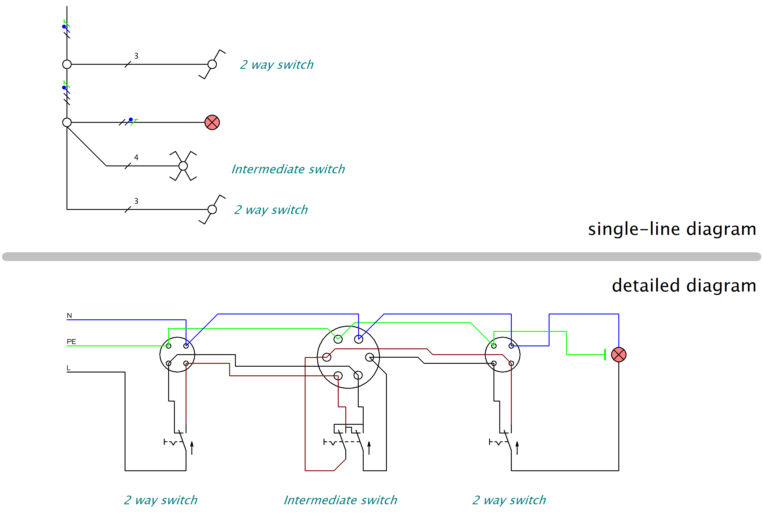
Single-line and Detailed Electrical Diagrams
ProfiCAD supports both single-line and multi-line (detailed) electrical schematics. The approach you choose depends on the level of detail your project requires.
Single-line | Detailed |
|---|---|
|
A simplified representation of an electrical system. Single lines depict connections between components like transformers, circuit breakers, switches, and loads. |
A comprehensive representation that uses specific symbols and lines to show physical connections, wiring, and components in full detail. |
| Gives you a high-level overview without showing the internal wiring of individual components. | Used for in-depth analysis, troubleshooting, and detailed design work. |
|
|
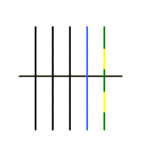
| Shows all wires of one cable as a single line. | Shows each wire as its own separate line. |
How to draw: |
|
|
Place
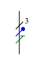
conductor protective conductor |
Draw the cable using the cable drawing tool. |
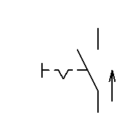
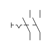
Symbols: |
|
switch single-pole, single-throw |
|

|
|
double-pole switch double-pole, single throw |
|

|
|
two-way switch single-pole, double-throw |
|

|
|
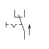
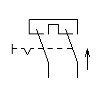
intermediate switch double-pole, double-throw |
|

|
|
transformer |
|

|

|
Example: the same wiring in both formats
Automatic cable length calculation for floor plans
When you draw electrical installation diagrams in floor plan view, the program automatically calculates approximate cable lengths. Floor plans typically use single-line drawing, where one connection represents one cable. The program calculates the cable length by multiplying the connection length in the drawing by the page scale.
How to display cable lengths:
- Create a connection list.
- Right-click on the header of the connection list table.
- Select "Add column" and choose the variable "_len".
For example, if you draw a 10 cm connection at a scale of 1:50, the program calculates a cable length of 5 meters (10 cm x 50 = 500 cm = 5 m). This length appears in the "_len" column of the connection list.