Cross-References
Wires
When two wires share the same name, they're considered connected (same potential). You set a wire's name in the Properties panel.
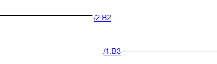
If a wire ends without a connection and another wire with the same name exists on a different page, a cross-reference to the other wire is automatically created.
A wire end pointing left or up links to previous page(s) of the project. A wire end pointing right or down links to subsequent page(s).
Symbols
A component is an electrical device that may consist of multiple symbols. For example, a relay coil (main symbol) and its contacts (subordinate symbols).
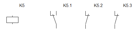
The main symbol gets a reference like K5. Subordinate symbols follow the pattern parent reference + dot + number (e.g., K5.1, K5.2). All symbols of a component share the same reference prefix.
Subordinate symbols are excluded from the bill of materials by default. To include them, check Show subordinate symbols in the bill of materials dialog.
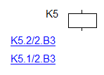
When you follow this naming convention, a reference table automatically appears beside each symbol that belongs to a component.
For example, the relay on page 1:
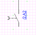
And its contacts on page 2:
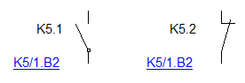
Cross-references use the format reference/page.zone, as defined by the EN 61082-1 standard, article 5.8.
Enabling and Updating Cross-References
Cross-reference generation is off by default. To turn it on, go to F12 - System - Symbols and enable Generate Cross-References of symbols and Generate Cross-References of wires.
If you move a symbol within the drawing, run File - Refresh Cross-References to update its zone.
Why do unwanted cross-references sometimes appear?
This happens when wires aren't properly attached to the symbol's connection points.
To fix this:
- a) Carefully place the wire end exactly on the symbol's connection point.
- b) If that doesn't help, redraw the wire.