Drawing electrical symbols
Creating a symbol
- Use the menu command
File-New symbol. - The symbol editor opens — you can recognize it by the blue ruler along the edges of the working area.
-
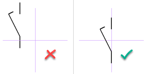
Draw the symbol using graphical objects (lines, rectangles, etc.). ⚠️ Place the symbol symmetrically on the axes of the working area — otherwise it will not be aligned correctly in the drawing.
- Save the symbol with
File-Save. Choose a descriptive name and save it to a suitable folder in the library. - Close the symbol editor (
Ctrl+W). - The symbol is ready to use!
Editing an existing symbol
This section describes how to open an existing symbol in the symbol editor, in other words how to launch the symbol editor to edit it.
- In the symbol palette or symbol search window, right-click the symbol and select
Open Symbol. - The symbol opens in the symbol editor. Make your changes.
- Save the symbol (
Ctrl+S) and close the editor (Ctrl+W). - ⚠️ Changes won't appear in existing drawings automatically. You need to delete the old symbols from your drawings and re-insert the corrected version.
Creating a symbol based on another symbol
If your new symbol is similar to one that already exists, it's best to start from a copy. This keeps dimensions, connection point positions, and overall style consistent across the library.
In the symbols palette, right-click the model symbol and select Create similar symbol.
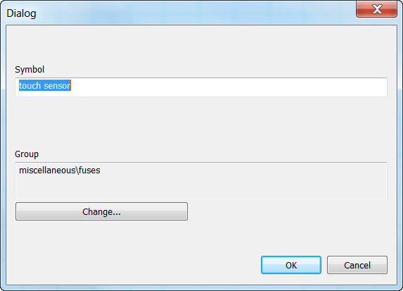
A dialog box appears. Enter the new symbol's title. If it should belong to a different group, press the Change button and select the target group.
Click OK to create the new symbol. Now just make the changes that differentiate it from the original and save.
Symbols are stored in files with the .ppd extension (normal symbols) or the .picd extension (integrated circuits).
Connection points
You draw connection points using this icon:  .
Connection points must be properly aligned. The figure below shows an incorrectly positioned connection point - this makes it impossible to wire the symbol because the wire to another symbol wouldn't be horizontal.
.
Connection points must be properly aligned. The figure below shows an incorrectly positioned connection point - this makes it impossible to wire the symbol because the wire to another symbol wouldn't be horizontal.
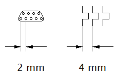
Most built-in symbols use connection point spacing of 2 mm or 4 mm. Stick with these values in your own symbols to keep everything consistent.
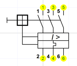
Connection point numbers in print reports are based on the order you inserted them into the symbol. To check this order, use View - Show connection point numbers. You can change the order using the arrows in the Explorer panel.
Test your symbol
Before using a new symbol in real drawings, test it in a blank drawing. Insert it in various positions, verify it can be wired correctly, and check that it looks consistent with existing symbols.
If you've created several symbols, you can print them all with Outputs - Batch print symbols to verify they look as intended.
Creating a copy of a symbol
Each symbol has its own internal identifier. The program uses this identifier when inserting symbols into a drawing.
For this reason, do not copy symbol files (*.ppd) directly in Windows Explorer. Doing so creates separate files that share the same internal identifier. The program then treats them as the same symbol, which causes incorrect behavior when inserting symbols into a drawing.
To make a copy of a symbol, open it in the symbol editor and use the File – Save As… command. This procedure creates the copy correctly.
Renaming a symbol
A symbol's name matches its filename, so simply rename the file in any file manager (e.g. Windows Explorer, Total Commander).
Moving a symbol to a different group
Move the file to a different folder using Windows Explorer or another file manager.
Deleting a symbol
Delete the file from the symbol library. You'll find the library path in File - Options - Paths.
You can use any file manager to organize symbol files.
Nested symbols
A symbol can contain other symbols. ⚠️ Nested symbols cannot contain text - this is a program limitation.
Which formats can ProfiCAD import symbols from?
You can use several formats to import symbols and add them to the ProfiCAD library:
- Native PPD format: ProfiCAD's basic format for storing and editing symbols. A symbol downloaded from a community library or created directly in the program is saved as a file with the .ppd extension.
- CAD formats (DXF and DWG): ProfiCAD can directly import simpler symbols and vector elements from the universal DXF and DWG formats.
- Raster images (PNG and JPG): a symbol can also be created by importing an ordinary image. In the symbol editor, just create a new symbol, insert a PNG or JPG image into it, and add the outlets, the schematic markings or any missing parts directly in the program.
