Line Styles in CAD Drawings
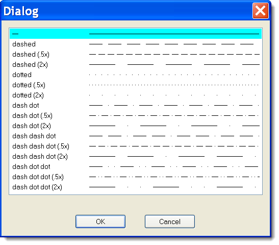
ProfiCAD supports these line types:
- solid
- dashed
- dotted
- dash-dot
- dash-dot-dot
- dash-two dots
How to Change the Line Type
- Select a line or connection.
- In the Properties panel, find "Line type".
- Click the button with 3 dots.
- Pick the line type you want from the dialog that appears.
Line Scale
You can adjust the size of individual line segments and the spacing between them using the line scale property in the Properties panel.
Custom Line Types
ProfiCAD uses predefined line styles in the LIN format, which is also used
by other CAD systems. Line style definitions are stored in .lin files
located in the _LIN folder of your library. If you have multiple .lin files
there, all their definitions are merged together -- so every style from every file becomes available.
LIN Format
A LIN file is a plain text file. Each line style is defined in two lines. The first line starts
with * followed by the style name, then a description separated by a comma.
The second line starts with A followed by a series of comma-separated numbers.
The first number is the length of a line segment. The next number is a space length.
Then another segment length, and so on. The unit is centimeters. A value of 0 means a dot.
Example:
*dash dot dot (2x), ____ . ____ . ____ . ___
A,1.0,-.5,0,-.5
The first line is the style name.
1.0 -- a 1 cm line segment
-.5 -- a 0.5 cm space
0 -- a dot
-.5 -- a 0.5 cm space
...then the pattern repeats.
For a real-world reference, take a look at the lines.lin file in the _LIN folder.