How to draw electrical wires between components

Basic procedure for drawing wires
1. From the Insert menu, select Conductor, click the button on the toolbar, or simply press the s key.
|
 |
| 2. The mouse pointer changes to the wiring mode cursor (soldering iron). |  |
| 3. Move the cursor to the connection point of the symbol where the wire should start. Click when the connection point turns red. |  |
4. Click to create a bend in the wire. If you made a wrong bend, press Backspace ⌫ to go back one step.
|
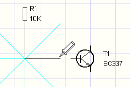 |
| 5. Move the cursor to the target connection point. Click again when the connection point turns red. | 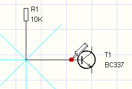 |
6. The wire is complete and the program immediately continues with the next one. To stop, press Esc.
|
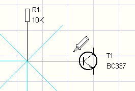 |
Connecting a wire to another wire
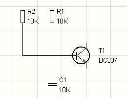
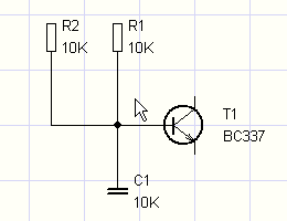
| 1. The procedure is the same as above, but instead of the target connection point of the second component, click on an existing wire at the point where you want to connect. The program automatically adds a junction dot, which marks the interconnection. | 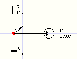 |
2. If two wires only cross (without being connected), no dot is created. To connect them at the crossing, use the Insert - Junction command or the  icon on the toolbar. icon on the toolbar.
|
 |
 |
Changing the wire shape
The shape of a wire can only be changed if its structure allows it.
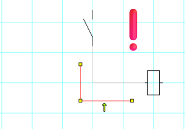
The wire must have at least three segments. In that case, you can change its shape by moving the middle segment, which is not attached to any symbol.
⚠️ Important:
Change the wire shape exclusively by dragging the resize handles.
If you grab the wire by its line and move it, the entire wire moves and becomes disconnected from the symbols.
The end segments are always attached to symbols, so their position cannot be changed.
Correct: changing the shape using a resize handle.Change the wire shape exclusively by dragging the resize handles. |
 |
Wrong: dragging the line → the wire becomes disconnected.Change the wire shape exclusively by dragging the resize handles. If you grab the wire by its line and move it, the entire wire moves and becomes disconnected from the symbols. |
 |
Sloped wires
Sometimes you need a wire that does not run only horizontally and vertically. The Insert - Sloping connection command lets you do that.
To make it clear which type of wire you are drawing, the program shows a different cursor for sloped and orthogonal wires:
 |
 |
| orthogonal wire | sloped wire |
Curved wires
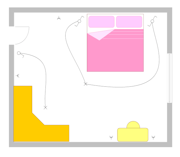
For organic-looking wires, use a Bézier curve (the Draw - Curve command).
⚠️ Curved wires cannot be connected to other wires – they work as standalone objects.
How to enter the number of a curved wire: In the Properties panel or with the Edit - Renumber wires function.
How to display the number in the drawing: Select the wire and click the Insert wire label link in the Properties panel. You can also display several numbers on one wire.
How to remove the number from the drawing: Select the wire number and press the Delete key.
Wires starting or ending "in the air"
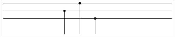
Sometimes you need a wire that does not lead to a specific component. In that case, start drawing with the right mouse button. Then continue as usual (bends with the left button), and to end the wire in the air, use the right button again.
Striped wires
If you need to distinguish conductors in the diagram with a colored stripe (e.g. the green-yellow protective conductor), use striped wires:

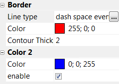
Procedure:
- Double-click the wire to open the Properties panel.
- Select the line type.
- Set the 1st color.
- Set the 2nd color.
- Turn on the 2nd color.
Wire shape
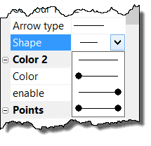
When you connect a wire to another wire, the program automatically adds a dot at the junction. If you don't want it displayed, turn it off in the Properties panel under Border/Shape.
How to show the direction of energy flow
Select the wire and choose the desired arrow shape in the Properties panel. The arrow is displayed at the end of the wire in the direction you choose.
