Drawing Terminal Blocks
Welcome to this instructional video on how to draw terminal blocks in ProfiCAD.
You may already have the terminal symbol in your library, but just to be sure, we'll show you how to draw it.
Start by selecting the File - New Symbol command to create a new symbol. The terminal is represented by a square with sides of 4 mm.
Add two connection points and a text with the terminal number.
Save the Symbol to the library.
Insert the terminal we just created into the drawing.
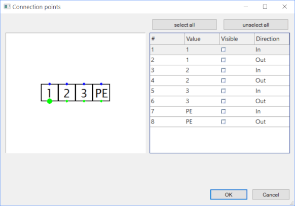
Right-click on the symbol to bring up the menu and select the menu item Setup connection points. Both connection points get the same number. Set one as input, one as output and hide the text labels.
Set the same terminal block designation to all terminals, that is, each terminal will have a reference of X1.
The terminal must have the terminal function set in the Properties panel.
Then the Start number text box appears in the Properties panel, in which we write the terminal number.
Let us add some more symbols.
I make a copy of the wiring to get another terminal block.
I set the reference "X2" to the terminals of the second terminal block.
Renumber the terminals of terminal board X2 so that each terminal has a unique number.
The terminal list includes terminal blocks X1 and X2.
Below the video you will find a summary of the entire procedure. I will be happy to answer your questions in the comments below the video. Let me know what you would like to see in the next video.
Thank you for your attention and have a nice day!