How to Draw Graphical Shapes
To draw graphical shapes, you can select the desired shape from the Draw menu or by clicking the corresponding button on the toolbar.
Selection Mode
To switch to Select mode, you can do one of the following:
- Press the
Esckey on your keyboard. - Click this icon:

- Move the mouse pointer to the toolbar area in the upper part of the main window.
 Line
Line
Click the mouse at the start and end points of the line. Press Esc to exit drawing mode.
 Polyline
Click to set the vertices of the line. To remove an unwanted segment, press the Backspace key. Press Esc to exit drawing mode.
 Curve
Curve
Use this function to draw connected Bezier curves. The curves are automatically linked for smooth transitions.
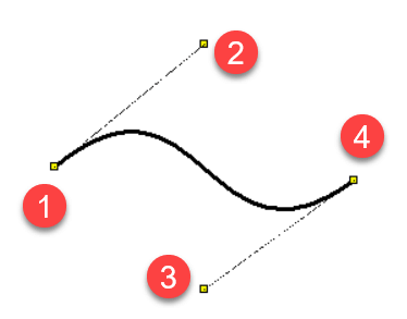
A Bezier curve is defined by four points: two endpoints (1) and (4), and two control points (2) and (3). The endpoints determine the ends of the curve, while the control points influence its shape by acting like magnets.
 Rectangle
Click the left mouse button at the upper-left and lower-right corners of the rectangle. You can then draw another rectangle or select a new graphic object from the menu.
 Rounded Rectangle
The process is similar to drawing a rectangle, but you define the rounding by clicking a third point.
 Arc Defined by Three Points
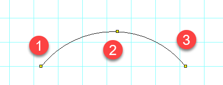
The first click sets the start point (1), the second click sets a point the arc passes through (2), and the third click sets the endpoint (3). Press Esc to finish drawing.


 Arc, Chord, and Pie
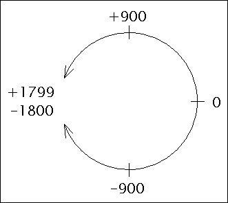
Draw these shapes like a rectangle but also define the starting and ending angles in the Properties panel. Angles are entered in tenths of a degree.
 Ellipse
Follow the same procedure as for a rectangle. Instead of a rectangle, an inscribed ellipse will be drawn.
 Polygon
Click to set the vertices of the polygon. After completing the polygon, press Esc to finish.
 Connection Point
Connection points, or outlets, are inserted only in the symbols editor (.ppd files). They are displayed in red for visibility and appear larger when selected.
 Junction
A junction indicates galvanic connection between two conductors. It can only be inserted where two wires cross.
How to Draw Arrows
Draw a line, Bezier curve, or arc, and select the arrow type in the Properties panel.
Modify arrow shapes by entering values for Scale X and Scale Y in the Properties panel. For example, a value of 1.23 enlarges the arrow by 23%.
Change the arrow's direction by clicking the flip arrow link in the Properties panel.
Orthogonal Drawing Mode
Activate orthogonal mode by pressing the Ctrl key while drawing. This mode constrains lines to vertical, horizontal, or 45° angles. Rectangles and ellipses become squares and circles.
Adding or Removing Points
This function allows you to add or remove points on a line or polygon.

Procedure:
- Select the line or polygon.
- Choose the
Edit – Add or deletemenu command. - Click on the line edge to add a point or on a node to delete a point.
- Press
Escto return to Selection mode.
Bezier Curve Control Points
Press the Ctrl key while moving a Bezier control point to ensure the opposite control point adjusts smoothly.
Dashed Line
Select a line and set the line type in the Properties panel. Adjust the Line type Scale property to modify segment sizes. For example, a value of 1.3 increases segment length by 30%.
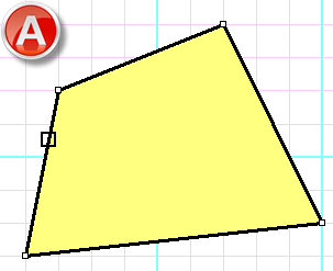
Hatching
Select a closed graphic object and choose a hatching type in the Properties panel.