What's New
ProfiCAD 13.5.4
4/29/2026General improvements and increased stability.
ProfiCAD 13.4.9
3/23/2026Bill of Materials Can Be Filtered by Pages
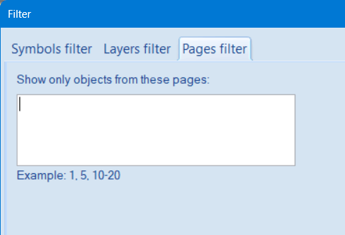
You can now filter the bill of materials not only by symbol names and layers, but also by pages.
Procedure:
- In the bill of materials, click the filter button
 .
. - A dialog box will appear. Select the "By Page" tab.
- In the field "Show only objects from these pages", enter page numbers separated by a comma (e.g. 1, 6), or a page range (e.g. 15-20), or a combination of both (e.g. 1, 5-12).
ProfiCAD 13.4.6
3/2/2026New Page Display Mode
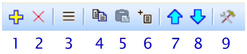
In the Pages panel, you can use button no. 9 to choose one of four page display modes:
- page sequence number
- short page name (the mode used in previous versions)
- sequence number, period and page name
- custom text using variables (e.g. {_po} - {project})

Write variable names between curly braces { and }.
This setting is saved separately for each document.
If the original mode suits you, there is no need to change anything in existing documents.
You can use the new, more descriptive display mode only for new documents.
Where to enter page variable values
Double-click a page in the Pages panel to open the dialog box.
Then switch to the Variables tab.

Page variables with print reports
When you insert a print report into the project using button 6, the program automatically sets these two variables:
- name – the name of the print report, e.g. "Bill of Materials" or "List of Wires"
- short name – a three-letter code according to the following table:
| code | report name |
|---|---|
| BOM | bill of materials |
| LOC | list of cables |
| LOT | list of terminals |
| LOP | list of pages |
| LOW | list of wires |
Colorful Explorer Display
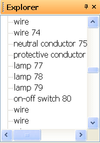
Items in the Explorer panel now have colored backgrounds according to their type for better clarity.
ProfiCAD 13.4.2
1/10/2026This update includes minor bug fixes and improves overall stability.
ProfiCAD 13.3.9
12/16/2025Export to DWG format
A new feature allowing export to the DWG format has been added to the program.
Procedure:
In the main menu, select Outputs → Export to DXF or DWG. A dialog box will open; choose the desired format, DXF or DWG, and click the Export button.
This new feature makes collaboration with other CAD applications easier and simplifies sharing your schematics.
ProfiCAD 13.3.7
12/8/2025New Keyboard Shortcuts
| Ctrl + L | Opens the Layers panel |
| Ctrl + F | Opens the Search panel |
ProfiCAD 13.3.1
11/9/2025This version improves the reliability and stability of exporting larger projects to PDF.
ProfiCAD 13.3
11/4/2025This update includes minor bug fixes and improves overall stability.
ProfiCAD 13.2.4
10/10/2025Faster rendering of wires and line objects
The new version significantly improves the rendering speed of wires, curves, and line-based objects. The optimization is most noticeable in complex drawings and at higher zoom levels.
ProfiCAD 13.2.1
9/9/2025You can now easily move multiple objects to a different layer.
How to do it:
- Make sure the target layer exists in the drawing.
- Select the objects you want to move.
- From the menu, choose Edit → Move selected objects to another layer.
- In the dialog, select the target layer and click OK.
ProfiCAD 13.1.7
8/25/2025If the list of wires contains the Length column, a row with the total length is displayed.
ProfiCAD 13.1.7
8/22/2025In the text editing dialog you can now choose whether the Enter key finishes editing or inserts a new line (Ctrl+Enter performs the opposite action).
ProfiCAD 13.1.5
8/4/2025This update includes minor bug fixes and improves overall stability.
ProfiCAD 13.1.4
7/24/2025Simplified Paper Size Settings
You no longer need to deal with two separate tabs – everything is now configured in one place.
Previously
The Page Setup used to have two tabs:
“Print Settings” – to select the paper size for printing
“Page Size” – to set the dimensions of the drawing on screen
To ensure correct output, the same paper size had to be set in both tabs, or the “Page Size” tab had to use the option according to print settings.
It was common for users to change the paper size only in the “Page Size” tab, which caused the drawing to print in the size specified in “Print Setup”.
Now
The Page Setup now contains only one tab: “Print Settings”.
You only need to set the paper size and orientation there. This is sufficient in nearly all situations.
What happened to the “Page Size” tab?
The tab still exists but is only accessible via a subtle button in the “Print Settings” tab. This helps prevent accidental misconfiguration by less experienced users.
The “Page Size” tab is only useful in special cases – for example, if you want to print a drawing scaled to a different format (e.g. A3 reduced to A4). In such cases, use the “Fit to sheets” option in the “Print Setings” tab.
ProfiCAD 13.1.2
7/7/2025New Design
The program has been completely redesigned, resulting in an improved appearance.

Dark Mode
The program supports dark mode, which can be activated using the menu command "View - Dark Mode". In dark mode, colors are displayed in inverse. Other colors used in the drawing are adjusted to maintain their contrast, meaning dark colors are converted to light and vice-versa.

Multiple Monitor Support
Open drawings are now displayed as tabs, making it easier to switch between them. Individual tabs can also be easily dragged and dropped to another monitor.

Simplified User Interface
For better clarity, rarely used symbols for gates and transformers have been removed from the toolbar. These elements are still available in the "Insert" menu.
The "Window" menu has been removed as it is no longer needed in the new tab-based user interface.
The "Textual Symbols" Panel Has Been Removed
The "Textual Symbols" panel was historically the first tool for inserting symbols into the drawing. Later, three better options were added:
The Symbol Search window always displays all relevant results from the entire database, regardless of their position in categories. This ensures that you never miss a needed symbol.
The Symbols panel allows for visual searching and works better with synonyms. This makes finding the correct symbol significantly easier, even if you are unsure of the exact name or prefer visual orientation.
The Favorites panel is continuously visible and allows for easy and quick insertion of symbols.
The removal of the "Textual Symbols" panel paves the way for further gradual improvements and the expansion of the functionality of the remaining three options. The goal is to enable you to work with the program even more comfortably and quickly in the future.
Title Block Preview
When selecting a title block, a preview is now displayed, making it easier to choose the correct one.

Keyboard Shortcuts
The new keyboard shortcut Shift + A displays the Attributes window, where you can edit the attributes for the currently selected symbol.
The new keyboard shortcut Shift + C displays the Connection points window, where you can assign numbers to the symbol connections for the currently selected symbol.
Cross-References
Cross-references between connections can include the connection name. Select the option {ref}/{pa}.{zone} in the program settings on the "Symbol" tab.
Further Improvements
In addition to the changes mentioned above, we have also worked on bug fixes and stability improvements for the program.
How to Install
Please back up your drawings and symbols before installation!
Since the program has been completely redesigned and now has a different look and changed operation, we recommend carefully testing the new version before purchasing.
You can install the program over the previous version. The upgrade is subject to a fee.
If you purchased the program after
How to Purchase an Upgrade to a New Version
If you have purchased a previous version of ProfiCAD, you can upgrade it with a 50% discount.
Install the new version and enter your license key. The program will display the discount code that you can use on the order page.
If you prefer to purchase the upgrade before installing this new version, please contact us via the contact form. We will gladly provide you with the discount code.